Published by Matt Fichera on 06/02/2020
How to Replace Parts on Your Dolphin Oasis Z5i Robotic Pool Cleaner
This is a walk through of how to disassemble the Dolphin Oasis Z5i robotic pool cleaner. Included below is a full video tutorial as well. You can purchase both the robot as well as parts for it directly on this website.
The Z5i is top-access allowing for the filter grids to be removed quickly and easily. The vehicle comes with the spring filters already in place. Here we are opening the robot and removing them for easy change out. The spring filter should be used the very first time you clean the pool and the ultra-fine cartridge filters should be used all summer. When you purchase, the Z5i also comes with a set of ultra-fine cartridges in an easy storage bag.
The mechanical components of a Dolphin Oasis Z5i robotic pool cleaner are easily viewed and quickly accessed by folding the handle of the robot down and turning the vehicle onto its back with the underneath facing up.
This machine has a really nice feature built into it. If all you are looking to do is replace the brushes, the rollers and the rings, you don’t actually have to take anything apart. All you will have to do is pop them out using a screwdriver to apply pressure and release the “C” clip on each side. You can then remove the roller from the vehicle and get a good look at where the roller was locked into its place.
If you are going to replace the rollers you would order the rollers parts. The brushes and the foam rings are separate parts and therefore would be ordered separately.
You really can see how easily the rollers pop off the “C” clips when we remove the front roller from the robot. If you are able to free one side, the other usually quickly follows. If you have done this correctly, then the roller tracks should be left still partially attached.
To remove these tracks, you’ll need a Phillips screwdriver and you’ll need to turn the robot onto its side. On each side there are four screws that need to be removed. If you’re using an electric drill instead of a screwdriver, be sure to set it at a low torque so you don’t snap the screw heads. Once all four screws are removed firmly grasp the side plate near the tracks and it pops right up and off.
Once you have the side plate off you can see the four places where it connects to the vehicle. And if you look underneath it will be clear where the side plate latches onto the body securely.
Once this is removed you can gain access to the gears, wheels, tracks, and pulley. At this time the robot’s tracks should be able to be removed freely.
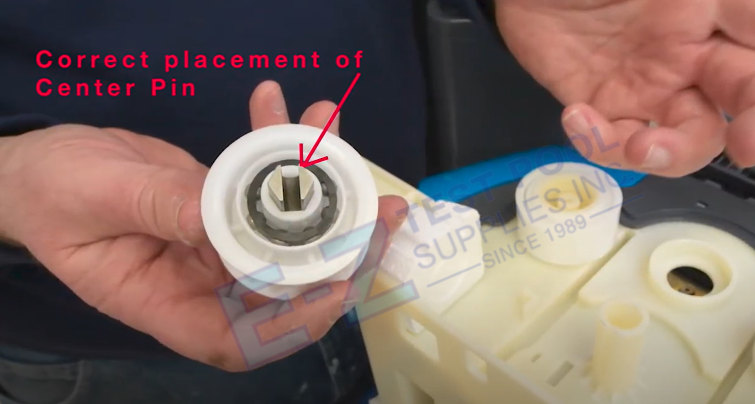
The first thing we do is remove the drive pulley then the guide wheels which are located on each side of the pulley. The pulley and the wheels are firmly attached but can easily be removed after applying some pressure. Be careful not to lose or damage the center pin located in the center of the pulley as the entire robot’s drive motor will not work without it. The guide wheels snap in and out of place using the built-in notches and can be changed out depending on their wear.
Located on the inside of the track, are two foam pieces, if you remove these, just be sure to put them back before reassembly. They only fit one way and will be self-explanatory.
At this time, one side of the robot is completely disassembled so we will flip it over to work on the other. We had mentioned earlier that if you are going to use an electric drill be sure that it’s set on a low torque. Another thing is that the drill may not work as the bit needs to reach in and grab the screw. In this case the drill doesn’t work as it’s too deep and we will go back to using the long screwdriver.
The disassembly of the second side will be exactly like the first but this robot features a dual drive motor so this side will also have a center pin. A good rule of thumb to remember with Dolphin/ Maytronics is any time that you have a split roller you’ll have a dual drive motor resulting in two center pins that are powered by two motors. This second side will have the same drive pulley, guide wheels, Styrofoam pieces and the same track.
To reassemble start with the re attaching of the guide wheels first. Located on each wheel are four notches that match up with four slots on the robot located under where the guide wheel sits. When you place the wheels back on, they should sit flat with the support structure. If there is a lip and it’s not flat then you know it’s not attached correctly.
Next up are reattaching the drive pin and pulley. The pin gets placed with the “hex” side of the pin facing down toward the machine then turn it over and place it back in pointing at the drive motor. Take your new track and wrap it around the drive pulley and place the pulley over the pin. At this time, you’ll want to make sure that the new track is threaded under the guide wheels but over the drive pulley. Also, make sure that the Styrofoam pieces are carefully placed back on each side as well. As previously mentioned, they only fit one way.
Now it’s time to re-connect the side plate. Make sure that the grooves that we mentioned earlier are lined up correctly. The two plastic cylinders located on the inside of the side plate will be lined up with and inserted into the middle of the two guide wheels. The plastic circle located in the middle of the inside of the side plate will reattach to the robot inside of the drive pulley. After making sure that all of this lines up correctly, you will need to provide a couple of light taps. It should make a clear snapping noise as the plate securely reattaches to the robot at all of the previously mentioned attachment points.
Don’t forget to put all four screws back in to each side. 8 screws in total. We find that it’s easier if you alternate distance points on each side while placing the screws back. Be careful not to crank the screws down too much.
You’re now ready to reassemble the other side. Flip the robot over onto its other side and start with the guide wheels again, then place the drive pin. Now its time for the pulley and track again. Place the track around the pulley like before. If you find this technique difficult, you can in fact reattached the drive pulley first and then thread the track afterwards. If you elect to attach the track this way, you will have to make sure that the track fits snug around the top of the pulley and firmly underneath the guide wheels, otherwise there will be what’s known as “skipping” of the track. Re align and snap in the side plate exactly like the first side and don’t forget about screwing it back in securely but not so tight that the plastic could crack.
Now we’ve reached the point that both side plates are back on. At this time, take the robot and turn it upside down making sure that the tracks are free.
We’ll be reattaching the rollers to both the front and back under sides of the robot. You can clearly see the “C” clips on the two front sides as well as the clip in the middle. That clip in the middle will connect to the roller at the point of space between the brushes and the “C” clips will connect to each end of the roller.
Line the roller up with each track, and roll it out to the end and drop it over the front, making sure that the tracks are still threaded over each end of the roller. At this time, firmly tap both sides into place inside of the “C” clips. Then, do exactly the same thing on the other side. The difference in tension on the second side will most certainly be noticeable. The reason for this is that the newer tracks are tighter and for the robot to function and maneuver correctly, the tracks need to be tight. If you are struggling with reattaching the second side, it’s alright to use a screwdriver as a lever to get the roller correctly connected. If you have done this correctly you should hear a firm popping sound on both sides as the rollers lock back into place.
During today’s demonstration we have left the plastic on the rollers. When you get this robot new make sure you remove all of the plastic before operating it.
How do you know when it’s time to change the tracks? If you can put your hand under it comfortable with little to no tension then it is time to replace the tracks. If you replace the tracks, always make sure you change out the bearings as well as this will save strain on the robot’s motor.
Lastly, turn the robot right-side up and place the filters back into place located at both the front and back of the vehicle’s top. On these filters you have two different sides. One is wide and one is skinnier. These align with what the inside of the robot looks like. As you can see, one side is wide and the other is just a slot. Because the Z5i has two cartridge filters, the sides actually alternate meaning that one cartridge goes into the machine one way and the other is placed the opposite way.
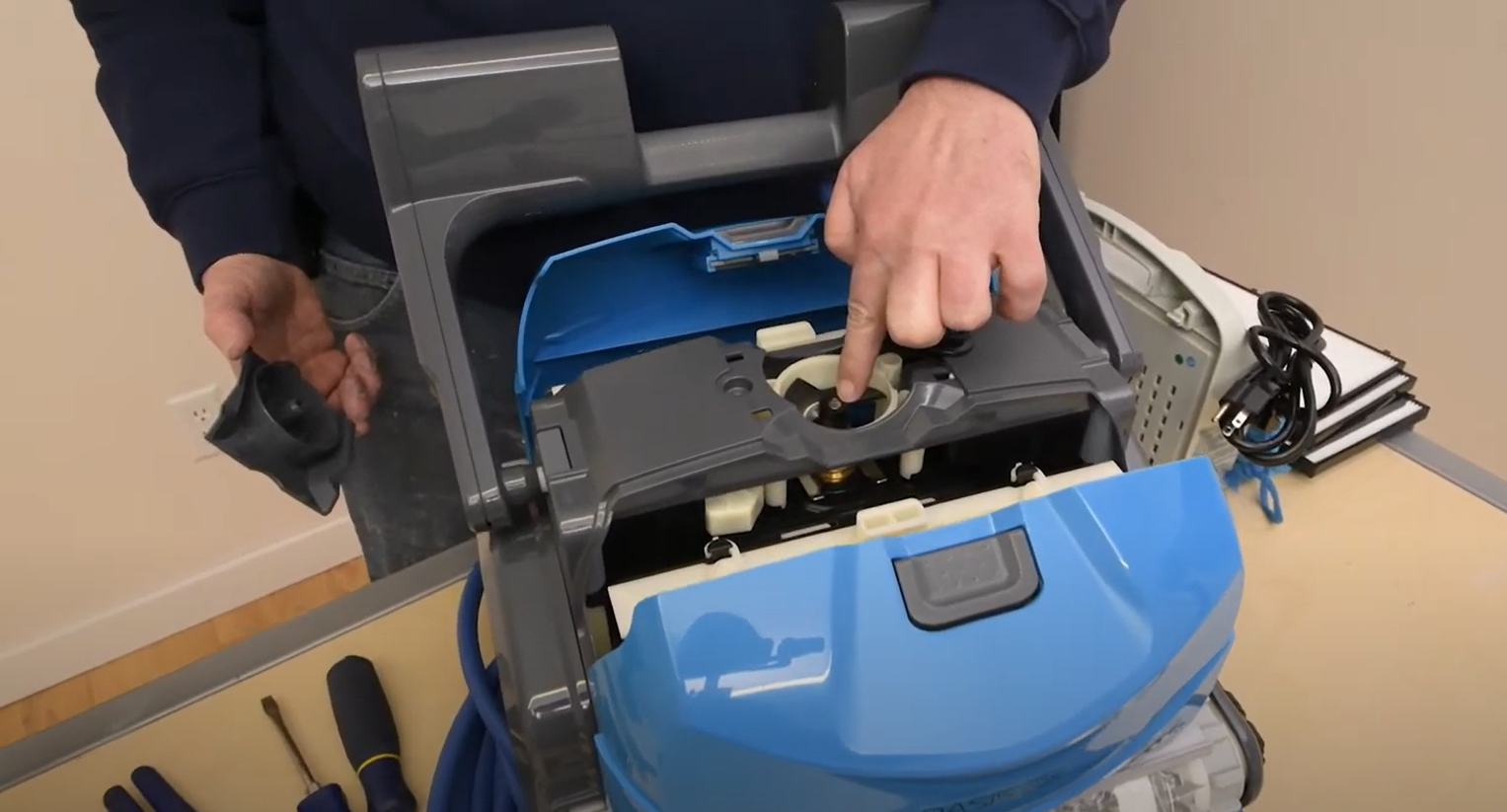
One more thing, you can remove the single screw on the top of the robot that accesses the impeller. That whole piece located right in the middle can be removed. By doing this you can clearly see into this compartment and clean and debris that may have collected in there. Inside, there’s another screw and by removing this one you can completely remove the impeller making it easier to clean as well. To reattach the exterior door, first slide the grooved side together and then place the screw back firmly but not too tight.
The Oasis Z5i is the workhorse of the Dolphin line, built on the most reliable Dolphin platform complete with dual commercial grade drive motors. It is offered exclusively online with a 3-year Limited Warranty
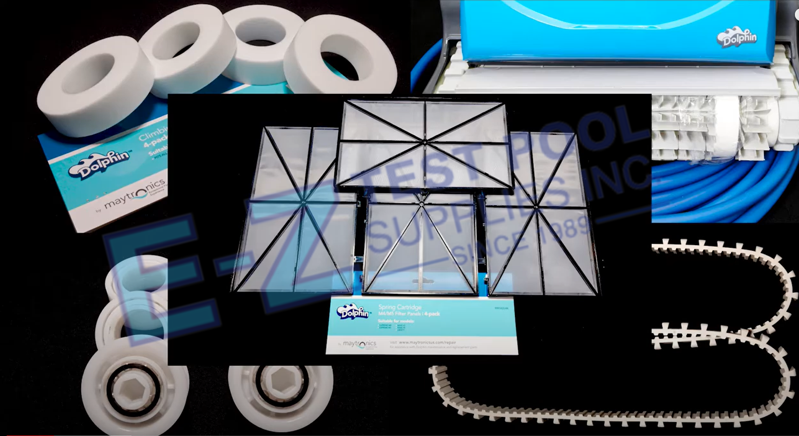
Parts that need periodic replacement due to wear on the Z5i include:


